Multi-Segment Metering Mod
Modification for M and K series Pentax lenses
NOTE: This modification is mostly obsolete now because will not work for Pentax Digital cameras: They use the digital data pin on the lens to get aperture information, not the multi-contact array discussed here.
Further notes:
• It will not permit shutter-preferred or programmed autoexposure on any camera.
• It will not have any effect on the ZX-30/MZ-30, ZX-50/MX-50, ZX-60/MZ-60 or the ist film camera.
• It will not work for the 50mm f/1.2 lens.
Many fine Pentax manual focus lenses are available on the used market, often at prices that belie their superb optical quality. Some are even superior to their modern, autofocus equivalents. The "K" and "M" series lenses, however, will only allow your modern camera to operate with center-weighted average light metering.
Early Pentax lenses can be modified to allow you to use the sophisticated multi-segment (matrix) metering capabilities of many modern Pentax film cameras. Note, however, that this does not include any of the new digital SLR's or any of the film cameras like the ist or ZX-60/MZ-60 that require lenses with an "A" aperture setting.
Technical Background
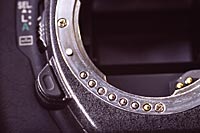
On cameras that have multi-segment metering, the microprocessor in the camera needs to know the minimum and maximum aperture of the lens being used. This is achieved with a series of contacts in the lower left-hand section of the lens mount on the camera body, which are visible upon removing the lens (top photo at right). The are 7 contacts in total, but not all of them are involved in multi-segment metering.
One of the 7 contacts transmits digital data from autofocus lenses and is not used for multi-segment metering.
Another one tells the camera if the lens is set to "A" for shutter priority or programmed autoexposure; this one also has nothing to do with multi-segment metering.
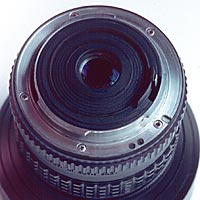
The remaining 5 contacts are where the min/max aperture data necessary for multi-segment metering are conveyed. On "A" series and later lenses, there are plastic insulators in one or more of the positions corresponding to these five contacts (second photo at right).
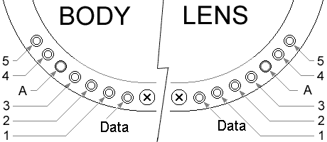
Pentax FA Series Lens Mount - Electronic Contacts
If there's a plastic insulator, that contact is open. If there's no plastic insulator (bare lens mount), the corresponding contact on the camera body is shorted to ground. The resulting pattern of grounded and ungrounded contacts constitutes a code which tells the camera body the maximum and minimum apertures of the lens in use. On a 50mm f1.4 there's only one insulator. On a 400mm f5.6 there are four. A 20mm f4.0 and a 300 f4.5 both have three insulators... but in different arrangements.
This is the information that allows multi-segment metering to work.
The table below shows the arrangement of insulators for various minimum and maximum lens aperture combinations. Find your lens' maximum aperture in the vertical column on the left and its minimum aperture in the top row. The cell at the intersection of these two will show the combination of insulating and conducting contacts, from 1 through 5 in order (with the "A" contact represented as an asterisk in the middle). A zero (0) represents a place where an insulator must be placed.
ApertureRange |
f/16 |
f/22 |
f/32 |
f/45 |
f/1.2 |
1 0 0 * 0 1 |
1 1 1 * 1 1 |
||
f/1.4 |
1 0 0 * 0 0 |
1 1 1 * 1 0 |
||
f/1.7 |
0 1 0 * 0 1 |
1 0 1 * 1 1 |
1 1 0 * 1 1 |
|
f/2.0 |
0 1 0 * 0 0 |
1 0 1 * 1 0 |
1 1 0 * 1 0 |
|
f/2.5 |
0 0 0 * 0 1 |
0 1 1 * 1 1 |
1 0 0 * 1 1 |
1 1 1 * 0 1 |
f/2.8 |
0 0 0 * 0 0 |
0 1 1 * 1 0 |
1 0 0 * 1 0 |
1 1 1 * 0 0 |
f/3.5 |
0 0 1 * 1 1 |
0 1 0 * 1 1 |
1 0 1 * 0 1 |
|
f/4.0 |
0 0 1 * 1 0 |
0 1 0 * 1 0 |
1 0 1 * 0 0 |
|
f/4.5 |
0 0 0 * 1 1 |
0 1 1 * 0 1 |
||
f/5.6 |
0 0 0 * 1 0 |
0 1 1 * 0 0 |
||
f/6.7 |
0 0 1 * 0 1 |
|||
f/8.0 |
0 0 1 * 0 0 |
Although the above data table clearly shows values that correspond to an f/1.2 aperture, the system in the camera body requires at least one non-conducting terminal to detect the presence of the aperture detection system. Therefore the 50mm f/1.2 lens cannot be used with multi-segment metering.
The Modification
If you drill a slight divot at each "insulator" position in the lens mount flange, corresponding to the pattern appropriate for that particular lens. Then put a drop of epoxy paint (see third photo at right) or other insulating material in the recess. It's a relatively simple procedure, but it requires precise positioning of the insulators in just the right locations.
|
|
|
|
|